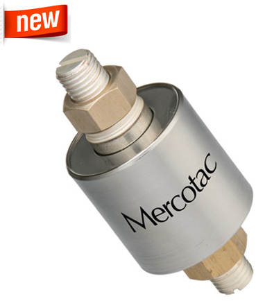
Mercotac Model 1500
One Conductor 500 Amper
| 
| 
|
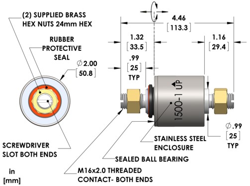
| 2 hex nuts included as shown - Available with external dust seal (Model 1500-1) Available with stainless steel ball bearing (Model 1500-SS)
|
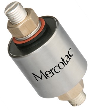
Mercotac Model 1500-1
One Conductor 500 Amper
with dust seal
| 
| 
|
| 2 hex nuts included as shown - Available with stainless steel ball bearing (Model 1500-1-SS) |
Mercotac model 1500 series are ideal connectors for high-power applications such as on plating electrodes and welding cable reels that require more power than the smaller Mercotac model 1250 series connectors. They come standard with a stainless steel housing. Available with stainless steel ball bearing (1500-SS or 1500-1-SS) (recommended for wet or corrosive environments).
| Model No. | Terminals | Voltage
AC/DC | Max.
Amp
Rating | Max.
Freq.
MHz | Contact
Resistance | Max.
RPM | Temp
Max. F (C) /
Min. F (C) | Rotation
Torque
(gm-cm) | Circuit
Separation |
| 1500 | 1 | N/A | 500 | 200 | <1m Ω | 300 | 140 (60) /-20(-29) | 750 | N/A |
| 1500-SS | 1 | N/A | 500 | 200 | <1m Ω | 300 | 140 (60) /-20(-29) | 750 | N/A |
| 1500-1 | 1 | N/A | 500 | 200 | <1m Ω | 300 | 140 (60) /-20(-29) | 750 | N/A |
| 1500-1-SS | 1 | N/A | 500 | 200 | <1m Ω | 300 | 140 (60) /-20(-29) | 750 | N/A |
-1" designator indicates an external dust seal
"-SS" designator indicates stainless steel ball bearing
Mercotac Slip Rings Model 1500 - 1 Connector 500 Amper
Suggested Mounting Methods
Model 1500 is typically mounted by the threaded stud on either end or by the steel body using a set screw. When mounting horizontally, mount the Mercotac so the body of the connector rotates.
Installation Notes:
the up arrow should not point below horizontal
do not solder to or bend connector tabs
avoid lateral forces and mechanical loads (overly stiff or tight wires)
do not rigid mount both ends of connector
limit mounting eccentricity (runout / wobble) to .005" (.13mm)
provide overload protection within the circuit
avoid vibration and bumping motions