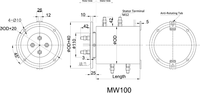
MW100 - Moflon Large Current Slip Ring
MW100 slip rings,Specail designed for 100A,mutiple 100A large current applications, specially used on wind turbine, can combine with signal rings,Pneumatic/Hydraulic Channel,and so on,provide the performance and quality needed in demanding environments. Costly downtime is eliminated by using fiber brushes and robust mechanical components in the large current slip ring design.
| Shared Specifications |
| Rings |
1~10(see table as above) |
Current |
Signal(2A),100A,Multiple 100A |
| Voltage |
600 VDC/VAC |
Max speed |
100RPM |
| Housing Material |
Aluminium Alloy |
Torque |
5N.m |
| Working life |
depends on working speed |
Contact material |
Precious Metal |
| Dielectric strength |
1000VDC@50Hz |
Lead Wire |
UL Teflon® |
| Insulation resistance |
1000MΩ@600VDC |
Lead Lengths |
250mm |
| Operating Temp. |
-40°C to 80°C |
Protection |
IP51 |
| Mechanical vibratio |
MIL-SID-810E |
Humidity |
10% to 90% RH |
| Materials |
Lead Free,RoHS compliant |
CE Certified |
YES |
|
Notes:
1)The operational life of the unit is dependent upon rotational speed, environment and temperature.
2)Electrical noise is dependent upon the rotating speed and current,voltage.
|
| PART # |
LENGTH
*OD(MM) |
SIGNAL
/2A |
CURRENT |
TOTAL
WIRES |
PART # |
LENGTH
*OD(MM) |
SIGNAL
/2A |
CURRENT |
TOTAL
WIRES |
| MW100-P01100-S04 |
106*100 |
4 |
1 wires*100A |
5 |
MW100-P02100-S04 |
106*100 |
4 |
2 wires*100A |
6 |
| MW100-P03100-S04 |
106*100 |
4 |
3 wires*100A |
7 |
MW100-P04100-S04 |
106*100 |
4 |
4 wires*100A |
8 |
| MW100-P05100-S04 |
136*100 |
4 |
5 wires*100A |
9 |
MW100-P06100-S04 |
166*100 |
4 |
6 wires*100A |
10 |
| MW100-P03200-S04 |
150*185 |
4 |
3 wires*200A |
7 |
MW100-P04200-S04 |
180*185 |
4 |
4 wires*200A |
8 |
| MW100-P05200-S04 |
210*185 |
4 |
5 wires*200A |
9 |
MW100-P06200-S04 |
240*185 |
4 |
6 wires*200A |
10 |
| MW100-P03300-S04 |
170*185 |
4 |
3 wires*300A |
7 |
MW100-P04300-S04 |
210*185 |
4 |
4 wires*300A |
8 |
| MW100-P01500-S04 |
47*60 |
4 |
1 wires*500A |
5 |
MW100-P02500-S04 |
180*245 |
4 |
2 wires*500A |
6 |
| MW100-P03500-S04 |
240*245 |
4 |
3 wires*500A |
7 |
MW100-P04500-S04 |
290*245 |
4 |
4 wires*500A |
8 |
Standard drawings:
12 wires for one group color. from 13 ... 24, repeat the same color as 1 ... 12,indicated with number code pipe.
| Lead wire Color codes |
| Rings# |
Color Code |
Rings# |
Color Code |
Rings# |
Color Code |
| 1 |
BLK |
5 |
YEL |
9 |
GRY |
| 2 |
BRN |
6 |
GRN |
10 |
WHT |
| 3 |
RED |
7 |
BLU |
11 |
PINK |
| 4 |
ORN |
8 |
PURPLE |
12 |
AZURY
|
- If you don't see what you want in this website,let us know; we may already have it designed or we will modify a design to meet your requirements. In many cases the specifications in the catalog can be changed to include bore size, circuits number, higher current/voltage,flange, lead wire length,shielding,connectors,higher speed,IP68,military grade,higher temperature, mixed with pneumatic/hydraulic capability. Please ask if you don't see exactly what you need as only a small fraction of our Moflon slip rings are included in this catalog!
-
-
-
- Optional flange mounting.
- Specified the wire exit direction.
- Can combine more wires:1-120Ring
- Specified connectors and Heat-shrink tube.
- Longer lead lengths available.
- Shielded cables
- Connectors
- Environmentally Sealed up to IP68@4Mpa
- Frequencies up to 500 MHz
- High-speed data transmission for fast Ethernet and EtherCat
- Signal, Coax, and Power combinations
- High Speed up to 20,000 rpm
- Thermocouples
- Shock, Vibration, and Temperature Qualified
- Pneumatic/Hydraulic Capability
- High temperature---up to 450 degree
- High Voltage & large Current(1000A)
- IP65,IP68 are avialable.
- Military Grade.
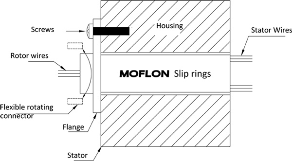
Flange Mounting Instructions
1. Align the mounting holes in the flange to mounting base and install flat washers and thread forming screws (NOT SUPPLIED) for plastic. Securely tighten screws.
2. Route the wiring and make the necessary connections. Do not allow the wiring to restrict free rotation of the slip ring.
3. Position a screw or dowel (NOT SUPPLIED) in the anti-rotation tab to the dimension as shown.
CAUTION: Because of possible geometric mismatching between the customer��s application and the slip ring, 'hard mounting' of both ends of the slip ring (i.e., securing the rotor and stator such that there is NO floating during operation) is not recommended and may cause premature failure
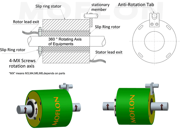
Shaft Mounting Instructions(For Through bore style)
1.Main shaft mouted units:
A.Position the slip ring in the desired location and tighten both set screws to the shaft.Maximum torque 25Ib-in(DO NOT OVER TORQUE)
B.Route the wiring and make the neccessary connections.Do not allow the wiring to restrict free rotation of the slip ring.Do not constrain wiring such that wire flexing occurs.Doing so will ultimately cause failure(breakage of the wiring).
2.Housing mouted units:
A.Anti-Rotation tap used for connecting the stator of slip ring with the stationary member of euipment
B.Route the wiring and make the neccessary connections.Do not allow the wiring to restrict free rotation of the slip ring.
Build On Your Request/Special requirements
MOFLON specialize in customized solutions, Now our models have over 12000, and over 80% model are customized on customer request and base on technology and full experience, our slip ring solution including traditionary carbon brush, gold wire contact, gold fiber brush contact, no contact transmit, each solution application depend on the customer real application request with economically, high quality and reliability.
MOFLON supply build-on-request service base on MW100 series, the delivery time of build-on-request is 2 weeks,and price is only 10%~30% more than the standard version.
Now, Let's start - how to build on request?
Customized Order Instructions:
MW100
Build-On-Request Flowing:
